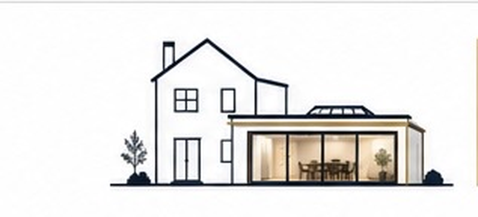
0.18, 0.15, 1.4: Meet U-values for extensions in England
England-focused guide to Approved Document L U-values for extensions: Table 4.2 limits, practical build-ups, a worked P/A floor example, and clear...
0.18, 0.15, 1.4: Meet U-values for extensions in England
Your extension must meet Table 4.2 of Approved Document L: external walls at 0.18 W/m²K, ground floors at 0.18 W/m²K, roofs at 0.15 W/m²K, windows and doors at 1.4 W/m²K (whole-unit), and rooflights at 2.2 W/m²K. These are the limiting values for new elements, not aspirational targets.
TL;DR:
- All new extension elements must meet strict U-value limits: external walls and ground floors at 0.18 W/m²K, roofs at 0.15 W/m²K, windows and doors at 1.4 W/m²K, and rooflights at 2.2 W/m²K, with no flexibility.
- Retained or renovated components follow higher thresholds, like 0.55 W/m²K for cavity fill walls and 0.30 W/m²K for internal or external insulation upgrades.
- The 25% glazing rule caps window and door areas relative to extension floor space, requiring better-performing units or increased insulation elsewhere to compensate if exceeded.
- Achieving compliant U-values depends heavily on insulation material choice, installation quality, and proper junction detailing, not just the calculations.
- Submitting comprehensive U-value calculations, material specs, and detailed junctions to building control before construction reduces delays and ensures compliance.
Table of Contents
- U-values for extension work: the official limiting figures
- Which values apply: new elements versus retained or renovated elements
- The 25% glazing rule and how to work around it
- Practical build-ups that actually hit the targets
- How to calculate compliance yourself, with a worked example
- What building control needs to see before approving your extension
- Practitioner perspective: keeping compliance simple on a rear extension
- Airtightness: the requirement most homeowners overlook
- Ventilation: the other half of a well-performing extension
- How long does compliance take, from design to approval?
- What does hitting these U-values actually cost?
- An honest editorial take on where homeowners get this wrong
- Getting a compliant extension without chasing paperwork yourself
- Sources
- FAQ
U-values for extension work: the official limiting figures
Building control will check your extension against one set of numbers, and there’s no room for interpretation on them. Table 4.2 of Approved Document L sets the ceiling for how much heat each new part of your building fabric is allowed to lose, measured in watts per square metre of surface per degree Kelvin of temperature difference (W/m²K). Lower is better. A wall with a U-value of 0.18 loses heat far more slowly than one at 0.30.
| Element | Limiting U-value | Measured on |
|---|---|---|
| External wall | 0.18 W/m²K | Net area, excluding openings |
| Ground floor | 0.18 W/m²K | Net floor area |
| Roof | 0.15 W/m²K | Measured on plan (not sloped area) |
| Windows and doors | 1.4 W/m²K | Whole-unit, including frame |
| Rooflights | 2.2 W/m²K | Measured on the horizontal |
A few clarifications save homeowners real confusion later. The window figure of 1.4 W/m²K is a whole-unit value, meaning frame and glass together, not the centre-pane figure glass manufacturers sometimes quote in isolation, which can look artificially good. If your designer instead references a Window Energy Rating, Band B or better broadly aligns with this threshold, and a Doorset Energy Rating serves the same purpose for entrance doors. Roofs are measured on plan area rather than the sloped surface, which matters if you’re specifying a vaulted or pitched extension roof, since the two figures diverge noticeably on a steep pitch. Table 4.2 itself is the reference point building control officers work from, so any specification quoting different numbers needs an explanation, not just a shrug.
Which values apply: new elements versus retained or renovated elements
Not every part of an extension counts as “new” in regulatory terms, and getting this distinction wrong is one of the more common ways homeowners misjudge their own compliance position. A new element is exactly what it sounds like: a wall, roof, or floor built from scratch as part of the extension.
New elements must hit the Table 4.2 figures covered above. Retained and renovated elements instead follow Table 4.3, which sets more forgiving thresholds because upgrading an existing structure to new-build standards isn’t always physically achievable or proportionate. Under Table 4.3, a wall upgraded via cavity fill needs to reach 0.55 W/m²K, while one upgraded using internal or external insulation needs 0.30 W/m²K. Renovated roofs need to reach 0.16 W/m²K, and renovated floors need 0.25 W/m²K.
Why the gap? Cavity fill alone can’t achieve the same performance as a full new-build cavity wall with modern insulation boards, so the regulations accept a lesser figure where it’s the only practical route. Internal or external insulation, by contrast, can get much closer to new-build performance, hence the tighter 0.30 W/m²K threshold for that method.
For most single-storey rear extensions, the practical reality is straightforward: the extension’s own walls, roof, and floor are new elements governed by Table 4.2, and Table 4.3 only becomes relevant if the project also touches the existing house fabric, such as removing an old external wall to create the opening into the extension. A SAP calculation (the government’s Standard Assessment Procedure) becomes necessary rather than a simple elemental check when the extension’s design departs significantly from notional values, for instance with an unusually high glazing ratio offset by superior wall performance elsewhere.
The 25% glazing rule and how to work around it
Glazing area in an extension can’t exceed 25% of the extension’s floor area, plus the area of any openings the extension covers, such as an existing patio door opening that gets absorbed into the new structure. This cap exists because windows and doors, even good ones, lose heat roughly eight times faster than a compliant wall does, so unlimited glazing would quietly undermine the whole point of Table 4.2.
Working out your allowance is simple arithmetic. A 20 square metre extension gives you a baseline allowance of 5 square metres of glazing. If that extension also covers an existing 3 square metre patio door opening in the original house wall, this area gets added, taking the total allowance to 8 square metres. Large sliding or bifold doors, popular in rear extensions for obvious reasons, can eat through that allowance fast, which is why glazing proportion needs deciding early in the design conversation rather than after the windows have been ordered.
If you’re set on more glass than the 25% rule allows, you have two routes. The first is specifying doors and windows with better performance than the 1.4 W/m²K minimum, since exceeding the standard on individual units can offset the extra area in an area-weighted calculation. The second is compensating elsewhere in the fabric, tightening the wall or roof U-value below 0.18 or 0.15 to balance the extra heat loss from generous glazing. Either route usually pushes the project from a simple elemental check into full SAP modelling, which your designer or architect will need to run. If daylight matters more to you than sheer glass area, it’s worth reading about rooflight sizing before assuming bigger doors are the only way to get a bright room.
Practical build-ups that actually hit the targets
Meeting a U-value on paper and meeting it on site are two different challenges, and the gap between them is almost always down to material choice and installation quality rather than the target itself being unreasonable.
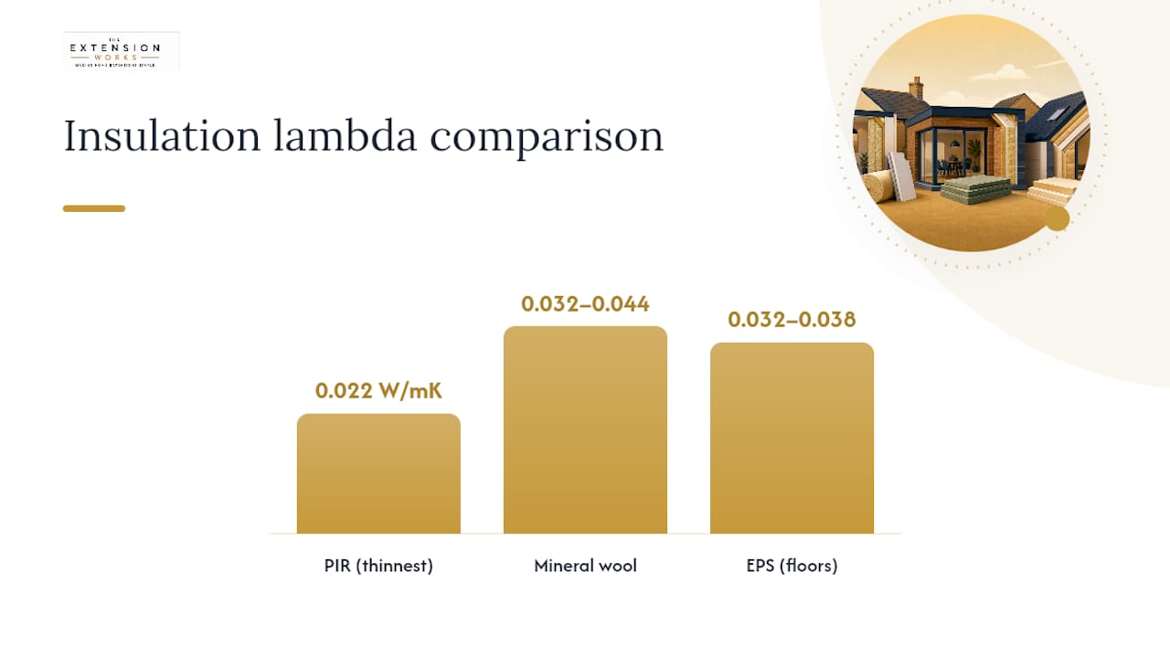
Three insulation types dominate UK extension builds, and their thermal conductivity, or lambda value, determines how thick your build-up needs to be. Rigid PIR board (polyisocyanurate) typically has a lambda around 0.022 W/mK, making it the thinnest option for a given performance level, which matters in extensions where you’re fighting for every centimetre of internal head height under a flat roof. Mineral wool sits at roughly 0.032 to 0.044 W/mK depending on density, cheaper per square metre but needing more depth to match PIR. Expanded polystyrene (EPS) falls in a similar range to mineral wool, around 0.032 to 0.038 W/mK, and is common in floor build-ups because it copes well with slab loading.
As a rough guide, a cavity wall using full-fill PIR board can reach 0.18 W/m²K with roughly 100 to 120mm of insulation, depending on the block and brick specification either side. A flat roof build-up typically needs 150 to 180mm of PIR to reach 0.15 W/m²K, while a solid ground floor might need 100mm of PIR or a thicker EPS layer beneath the slab to hit 0.18 W/m²K. These figures shift with every manufacturer’s exact product, so always check the datasheet lambda rather than assuming one PIR board performs identically to another.
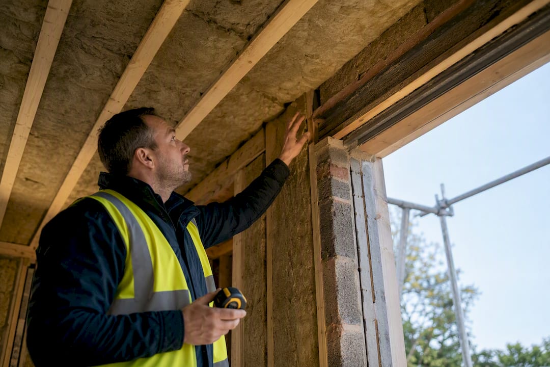
Installation quality is where good specifications quietly fail. A gap behind a PIR board, a compressed roll of mineral wool squeezed into too shallow a joist void, or an uninsulated junction where a new wall meets the old house, can all drag the real-world performance well below what the calculation promised. None of these show up on a spec sheet. They show up on site, and usually only if someone is looking for them.
Before signing off any builder’s quote, ask these questions:
- What is the lambda value of the insulation specified, and can I see the manufacturer’s datasheet?
- What area and U-value calculation supports this build-up, and does it match Table 4.2 or 4.3?
- Who is installing the insulation, and are they certified for the product being used?
- How will junctions between new and existing structure be detailed to avoid gaps?
- Will the finished U-values be confirmed in writing as part of the building control submission?
Pro Tip: Ask for the area calculation, not just a headline U-value. A builder who can show you area × U-value working for each element is far more likely to have actually checked compliance than one who simply states “we’ll meet Part L”.
How to calculate compliance yourself, with a worked example
You don’t need to be an engineer to sanity-check a designer’s figures, and doing so takes ten minutes with a calculator.
- List every new element in the extension: walls, roof, floor, windows, doors, rooflights.
- Multiply each element’s area by its U-value to get its heat loss coefficient.
- Sum these figures across the whole extension to get total fabric heat loss.
- Compare against the notional design, a hypothetical extension of the same dimensions built exactly to Table 4.2 limits, which acts as the backstop your real design must not exceed overall even if individual elements trade off against each other.
- Flag any element below Table 4.2 standard and confirm what’s compensating for it elsewhere.
Floors work slightly differently because heat loss through the ground depends on the floor’s perimeter-to-area ratio, known as P/A. A small extension with a long, thin footprint loses proportionately more heat through its edges than a square one of the same area, so the required insulation thickness varies with shape, not just size. Local authority guidance from Brent sets out worked examples of exactly this calculation for typical extension footprints.
Take a rear extension measuring 6 metres by 4 metres, giving a floor area of 24 square metres and a perimeter of 20 metres. That’s a P/A ratio of 0.83. A higher P/A ratio (a thinner, more elongated shape) generally needs a slightly thicker or better-performing floor insulation than a squarer footprint of the same area to reach 0.18 W/m²K, because more of the floor sits close to a cold edge. Your designer’s floor U-value calculation should state the P/A ratio explicitly. If it doesn’t, ask for it.
For a straightforward single-storey rear extension with glazing under 25% and no unusual geometry, the elemental method above is normally sufficient. Full SAP modelling becomes necessary once you’re trading performance between elements, exceeding the glazing allowance, or the local authority specifically requests it.
What building control needs to see before approving your extension
Your building control submission needs to demonstrate compliance on paper before a single insulation board goes up, not after — if you’re unsure about which projects require approval, our guide on building regs approval for a bathroom can help clarify the process. Submitting incomplete information is one of the most common causes of delay on straightforward extension projects.
At minimum, expect to provide scaled drawings showing the extension’s construction, U-value calculations for every new element (walls, roof, floor, windows, doors, rooflights), and, where relevant, a SAP report covering the whole extension. Material specifications need to state the insulation product, its thickness, and its lambda value, not just a generic description like “150mm insulation” with no product named. Installer certification, particularly for anything requiring competent-person scheme registration, should also be part of the package. Our guide to building regulations completion certificates covers the wider approval process in more detail.
On site, building control officers typically check continuity of insulation at junctions, around openings, and where the extension meets the existing house, since these are the points most prone to gaps and cold bridging. They’ll also want to see the final paperwork reconciling what was actually installed against what was specified, so keeping manufacturer datasheets on site throughout the build, not just at the design stage, avoids awkward gaps in the record when the inspector calls.
Submit your U-value calculations before work starts wherever possible. A plans check ahead of construction catches mismatches while they’re still a drawing-board problem rather than a site problem, which is considerably cheaper to fix.
Practitioner perspective: keeping compliance simple on a rear extension
A design-and-build provider handling everything in-house has one structural advantage over a fragmented supply chain: nobody can quietly downgrade a specification between design and site without someone else in the same team noticing.
That matters more than it sounds. On a project with separate architect, builder, and insulation subcontractor, a U-value calculation done at design stage can drift by the time materials get ordered, sometimes because a product goes out of stock and gets swapped for something similar but not identical on lambda. The Extension Works structures its quotes to show the insulation specification, the glazing proportion modelled in the live 3D visualisation, and the supporting U-value calculations together, so what the homeowner sees at quote stage is what building control sees at submission stage. That consistency reduces the chance of a costly on-site respecification.
For homeowners who want to go deeper on the technical side, particularly where thermal detailing meets structural design at junctions and openings, our piece on structural calculations for extensions covers how those two disciplines interact in practice.
Airtightness: the requirement most homeowners overlook
U-values measure how well your insulation slows heat loss through the fabric itself, but heat also escapes through gaps, draughts, and poorly sealed junctions, which is a separate performance requirement entirely. Approved Document L requires reasonable provision for limiting unwanted air leakage, and while a single-storey rear extension usually doesn’t trigger mandatory pressure testing on its own (that’s typically required for new dwellings or extensions above certain thresholds agreed with building control), the underlying standard still applies.
Good airtightness detailing means sealed junctions where the new extension meets the existing house, taped and lapped membranes around the structure, sealed service penetrations where pipes and cables pass through the building fabric, and properly fitted, draught-sealed windows and doors. Skipping these details doesn’t just waste energy. It undermines the U-value calculation itself, because a wall that performs at 0.18 W/m²K on paper but leaks air through unsealed junctions won’t deliver anywhere near that performance in practice.
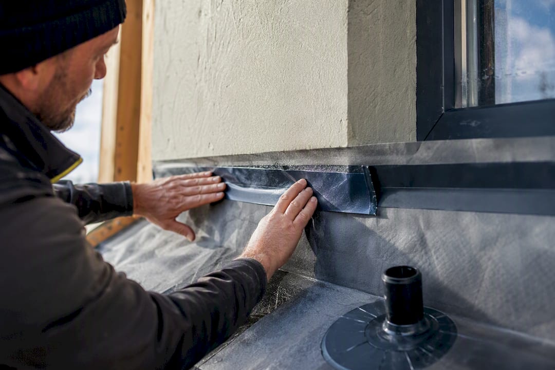
Ask your builder how airtightness will be achieved at each junction, particularly where the extension roof meets the existing wall and where new floor meets old. If your local authority does require a pressure test for your specific project, factor that into your programme early, since a failed test means opening up finished work to find and seal the leak, which is far more disruptive than getting the detailing right the first time.
Ventilation: the other half of a well-performing extension
A more airtight, better-insulated extension holds warmth in more effectively, but that same airtightness reduces the natural ventilation older homes have historically relied on through gaps and draughts. Building Regulations Part F covers ventilation specifically, and it works alongside Part L rather than against it: the tighter your fabric, the more deliberate your ventilation strategy needs to be.
For most single-storey rear extensions, particularly kitchen-diners, this typically means background ventilation (trickle vents in window frames) combined with intermittent extract ventilation, usually a mechanical extractor fan in the kitchen or over a hob, sized to the room’s use. Larger or more airtight extensions sometimes warrant mechanical ventilation with heat recovery, which extracts stale air while recovering some of its warmth to preheat incoming fresh air, though this is more common in whole-house retrofits than single-storey additions.
The practical point for homeowners is this: don’t let your builder treat ventilation as an afterthought bolted on once the insulation and windows are decided. A well-sealed, well-insulated extension with inadequate ventilation risks condensation and, over time, damp and mould, particularly in kitchens generating steam daily. Ventilation strategy should be part of the same design conversation as your U-values, not a separate decision made after the walls are up.
How long does compliance take, from design to approval?
Getting U-value compliance right doesn’t have to be a slow process, but it does need to happen at the right point in the programme rather than being squeezed in afterwards. A typical single-storey rear extension moves through initial design and 3D visualisation over one to two weeks, followed by preparation of technical drawings and U-value calculations, often another one to two weeks depending on complexity and whether planning permission or a permitted development route is involved.
Building control submission, whether via the full plans route or building notice, typically takes several weeks for a formal decision once complete information is submitted, though a full plans application allows queries to be resolved before construction starts, which most homeowners find preferable given the cost of unwinding mistakes mid-build. Construction itself for a typical single-storey rear extension runs roughly eight to twelve weeks depending on scale and specification, with building control inspections happening at key stages, foundations, damp-proof course, insulation before it’s covered, and final completion.
The single biggest cause of delay isn’t the U-value calculation itself. It’s incomplete or inconsistent paperwork submitted late, forcing back-and-forth queries with building control that could have been resolved at design stage. Getting drawings, specifications, and U-value calculations finalised and internally consistent before submission is the single most effective way to keep the whole programme on track.
What does hitting these U-values actually cost?
Insulation to meet Table 4.2 standards isn’t the budget-breaking line item homeowners sometimes fear, but it isn’t free either, and the cost varies more by build-up choice than by the U-value target itself.
Material costs scale with the insulation type chosen. PIR board costs more per square metre than mineral wool or EPS, but its thinner profile can reduce other costs, less brickwork or blockwork needed to achieve the same cavity width, more usable internal floor area under a flat roof. Labour costs for careful installation, properly fitted boards with sealed joints, correctly detailed junctions, don’t typically add a large premium over sloppy installation, but they do require a competent, careful team rather than the cheapest available. This is where corner-cutting most often shows up later as a compliance or performance problem, not in the material spec itself.
Testing costs are usually minimal for a typical single-storey rear extension, since mandatory airtightness pressure testing isn’t standard for this scale of project in most cases, though building control fees for plan checking and site inspections apply regardless of your U-value strategy. The real cost risk isn’t the insulation, it’s rework: opening up a wall or roof after a failed building control inspection because a junction wasn’t detailed correctly the first time. That kind of remedial work, involving both materials and labour a second time, dwarfs whatever was saved by skimping on the original specification.
An honest editorial take on where homeowners get this wrong
Most guidance on U-values for extensions treats the Table 4.2 figures as the whole story, and that’s the part I’d push back on. The numbers themselves are simple enough that any competent designer will meet them on paper. The gap between a compliant specification and a compliant building almost always opens up during installation, not design.
If you take one thing from all of this, make it the P/A floor calculation and the habit of asking for area × U-value working rather than a bare “we’ll meet Part L” assurance. That single request filters out a surprising number of vague specifications before they become expensive site problems. The glazing rule deserves more attention too. Sort the glazing proportion out first, and everything else about compliance gets easier.
— Esskay
Getting a compliant extension without chasing paperwork yourself
This platform provides an alternative to coordinating separate architects, builders, and insulation subcontractors, aiming to keep U-value figures consistent through the process. Quotes generated through the platform’s instant online tool include a specification, glazing proportion, and material detail already modelled in the live 3D visualisation, with pricing and warranty details provided by the service.

Because design, planning, and construction are managed cohesively, the specification provided at quote stage is intended to match what gets built and submitted to building control, avoiding inconsistent changes. That removes a genuine source of risk for homeowners who don’t want to become part-time compliance officers on their own project. If you’re ready to explore options for a single-storey rear extension, you can get an instant quote showing design and glazing proportion before committing to anything.
Sources
Approved Document L is the primary legal reference for every figure in this guide, and it’s worth downloading directly from Gov rather than relying on a secondhand summary, since Tables 4.2 and 4.3 sit within the full PDF alongside the wider context for when each applies.
Local authority guides add practical worked examples the national document doesn’t provide in the same depth. Brent Council’s U-value guide is a good example of this, walking through calculations for typical extension scenarios. Trade summary tools such as TradeCalculator’s Part L reference and insulation calculators like BuildWiz are useful for cross-checking a builder’s numbers quickly, though the Approved Document itself remains the figure that matters if a dispute ever arises with building control.
- Approved Document L (Conservation of fuel and power) — Volume 1: Dwellings (2021 edition incorporating 2023 amendments)
- U-value guide for domestic building work — Brent Council (Jan 2024)
- Building Regs U-values: Current wall, roof & floor targets | TradeCalculator
FAQ
What is the 3 metre rule for extensions?
The 3 metre rule relates to permitted development limits, not U-values: a single-storey rear extension on an attached house can extend up to 3 metres beyond the original rear wall without planning permission, or up to 6 metres under the prior approval (larger home extensions) scheme. It has no bearing on the thermal performance figures your extension must still meet under Approved Document L regardless of which permitted development route applies.
How do I achieve a 0.18 U-value cavity wall?
A full-fill cavity using PIR board with a lambda around 0.022 W/mK typically reaches 0.18 W/m²K with roughly 100 to 120mm of insulation, though the exact depth depends on the specific block, brick, and board combination. Always check the manufacturer’s datasheet for the exact lambda value rather than assuming a standard thickness will work across every product.
What are the U-values required for the Future Homes Standard?
The Future Homes Standard applies primarily to new-build dwellings rather than extensions to existing homes, which continue to be governed by Approved Document L’s Table 4.2 and 4.3 figures covered throughout this guide. Extension projects should work to the current ADL limiting values rather than new-build standards, and your building control officer will confirm which regime applies to your specific project.
How do I achieve a 0.11 U-value roof?
A U-value tighter than the 0.15 W/m²K Table 4.2 minimum for extension roofs would typically require a thicker PIR build-up than usual, or a combination of insulation layers above and below the roof structure.
What does The Extension Works charge to start a project?
The Extension Works uses a £499 one-off booking fee to begin the design and planning process once a homeowner is ready to proceed from an instant quote. The full project price is fixed and VAT-inclusive, generated instantly through the online quote tool based on your specific design and specification.