
Planning permission drawings: a homeowner's 2026 guide
Navigate your home extension with ease in 2026 using our complete guide on planning permission drawings. Ensure your application is valid!

Planning permission drawings: a homeowner’s 2026 guide
Planning permission drawings are the technical plans and maps legally required by your Local Planning Authority before you can build a home extension. They must show your existing property and the proposed changes at precise metric scales, with consistent site boundaries across every document. Get them wrong and your application is invalidated before a planning officer even reads it. This guide covers every drawing type you need, the legal standards each must meet, and the mistakes that most commonly delay approvals for homeowners in Morden and across the UK.
What types of drawings are required for planning permission?
A valid planning application for a home extension in 2026 requires several distinct drawing types, each serving a specific purpose for the Local Planning Authority. No single drawing tells the whole story. Together, they build a complete picture of your site, your existing property, and exactly what you intend to build.
Location plans and block plans
The location plan sits at the broadest scale. It shows your property in relation to the surrounding street network, typically drawn at 1:1,250. This tells the planning officer precisely where your site sits within the neighbourhood. The block plan zooms in, drawn at either 1:500 or 1:200, and shows your plot boundaries, the footprint of all buildings on the site, access points, and the proposed extension outline. Both are mandatory, but they serve entirely different purposes. The location plan establishes context; the block plan establishes detail.
Floor plans, elevations, and sections
Architectural drawings for planning sit at a finer scale, typically 1:50 or 1:100. Floor plans show internal layouts and room dimensions, with clear annotation distinguishing existing walls from proposed new build. Elevations show every external face of the building, including material finishes, window positions, and heights. Sections cut vertically through the building to reveal floor-to-ceiling heights and the relationship between your extension and neighbouring properties. For loft or roof-space work, cross-sections are not optional. They must demonstrate a minimum headroom of 1.5 metres to satisfy height regulations.

Summary of drawing types and their roles
| Drawing type | Typical scale | Primary role |
|---|---|---|
| Location plan | 1:1,250 | Shows site in street context |
| Block plan | 1:500 or 1:200 | Shows plot boundaries and extension footprint |
| Existing floor plans | 1:50 or 1:100 | Records current internal layout |
| Proposed floor plans | 1:50 or 1:100 | Shows new layout with annotated changes |
| Elevations (existing and proposed) | 1:50 or 1:100 | External facades, materials, and heights |
| Cross-sections | 1:50 or 1:100 | Vertical detail, headroom, neighbour impact |
What are the legal requirements for valid planning drawings?
The legal standards for planning application drawings are not guidelines. They are pass-or-fail criteria applied during the validation stage, before your application is even registered.
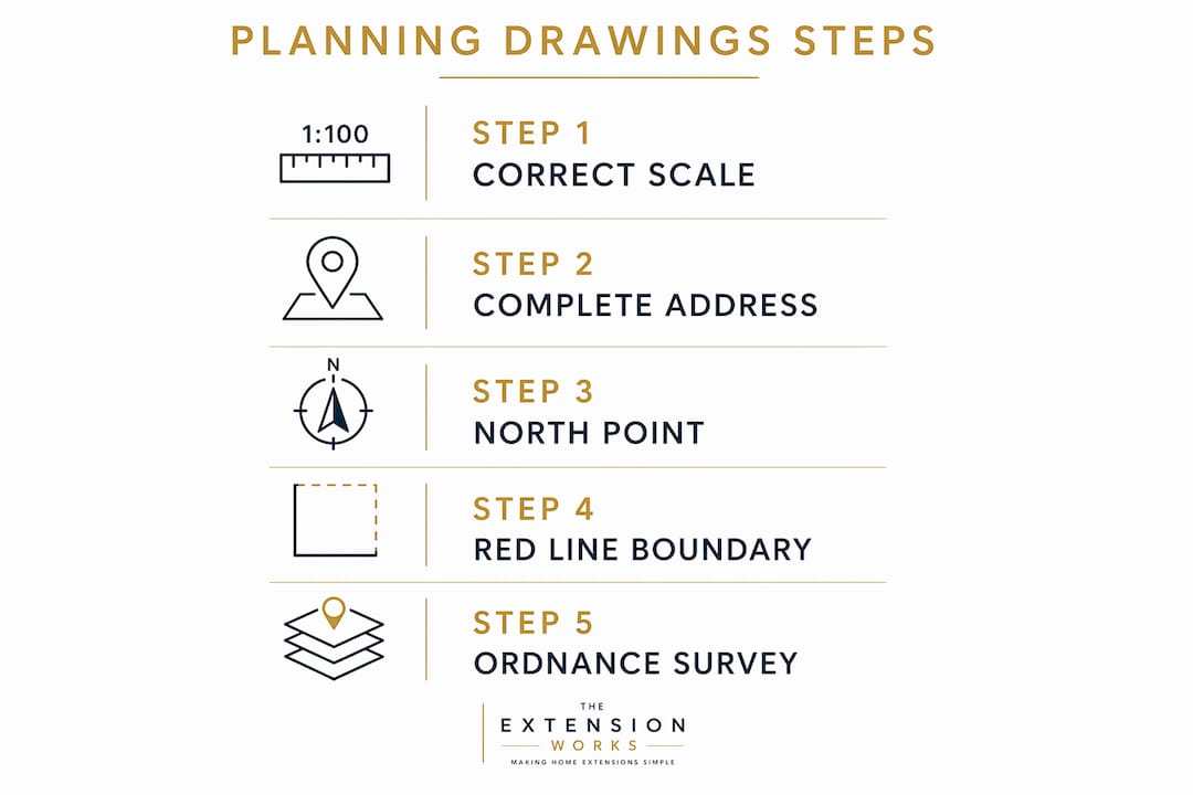
The most fundamental rule is scale. Metric scale drawings are mandatory for all planning submissions. Every drawing must include a printed scale bar and state the original paper size. This matters because digital files are routinely printed at different sizes, and a scale bar is the only reliable way to verify dimensions. Any drawing marked “Do Not Scale” is automatically invalidated. That annotation, common on architect-produced drawings intended for construction, has no place on a planning submission.
Map sources carry their own legal requirements. The Ordnance Survey holds copyright over the base mapping used in location and block plans. Plans using unlicensed maps such as Google Maps or Land Registry data are rejected outright. You must purchase your location and block plans from a licensed Ordnance Survey data supplier. This is not a technicality. Councils enforce it consistently.
Every drawing must also carry a north point, the full site address, and a drawing reference number. These details allow planning officers to cross-reference documents quickly and confirm they are reviewing the correct version.
Pro Tip: Before submitting, print each drawing at its stated paper size and physically measure a known dimension against the scale bar. If the numbers do not match, the drawing has been exported at the wrong scale and will fail validation.
The red line boundary on your block plan and location plan must enclose all land needed for the development, including the full garden, driveway, and any side access routes. The red line must include the full planning unit, not just the extension footprint. Omitting part of your own land is one of the most common and easily avoided errors.
Common mistakes in planning permission drawings
Most planning applications that fail at validation do so for reasons that are entirely preventable. The errors below account for the majority of initial rejections.
-
Mismatched boundaries across drawings. The red line on your location plan, the boundary on your block plan, and the footprint shown on your elevations must all agree exactly. Mismatches between these documents create reliability concerns for planning officers and trigger immediate requests for revised drawings.
-
Incomplete red line boundaries. Homeowners often draw the red line around the extension alone. The boundary must encompass the entire planning unit, including the house, garden, and all access routes relevant to the development.
-
Unlicensed map sources. Downloading a map from Google Maps or taking a screenshot from Land Registry and using it as your location plan will result in rejection. Only Ordnance Survey licensed data is accepted.
-
Missing or incorrect scale bars. Failure to include scale bars leads to automatic invalidation. Every drawing must state its scale and include a printed bar, not just a written note.
-
No cross-sections for roof work. If your project involves any roof-space conversion, omitting the section drawing is a guaranteed rejection. The section must show headroom clearly.
-
Inconsistent documentation across related projects. If you are applying for a rear extension and a side extension at the same time, both sets of drawings must share an identical site baseline. Conflicting site plans across two applications on the same property create serious validation problems.
Pro Tip: Create a single master site plan at the outset of your project and use it as the base for every drawing. Any change to the site boundary or footprint must be updated across all documents simultaneously.
How to prepare planning drawings effectively
Preparation order matters. Rushing into architectural drawings before you have accurate site maps is the single biggest source of the consistency errors described above.
Start by purchasing a licensed location plan and block plan from an Ordnance Survey approved supplier. These become the fixed reference for everything that follows. Your architect or designer then works from these maps, not from memory or rough measurements. This sequence prevents the boundary mismatches that cause most validation failures.
When engaging a designer, confirm they are familiar with your local council’s specific validation checklist. Requirements vary between authorities. Morden falls under the London Borough of Merton, and Merton’s checklist specifies its own preferred drawing formats and submission requirements. A designer who works regularly with Merton will know these nuances.
Digital tools improve accuracy considerably. CAD software allows designers to draw at true metric scale and export at any paper size without distortion. BIM platforms go further, linking floor plans, elevations, and sections so that a change to one view updates all others automatically. This is the most reliable way to maintain consistency across a full drawing package.
Parallel development of related schemes on the same site is strongly recommended when you are considering more than one extension. Developing a rear extension and a side return simultaneously, using one shared site baseline, prevents the conflicting documentation that arises when each scheme is drawn independently.
Before submission, check that every drawing carries the same site address, the same north point orientation, and the same boundary line. Cross-reference the floor plan footprint against the block plan. Measure the elevation heights against the section. These checks take less than an hour and can save weeks of delay.
You can also review the current extension size rules before finalising your drawings, as permitted development limits directly affect what your proposed plans need to show.
Key takeaways
Consistent, correctly scaled planning permission drawings are the single most important factor in getting a planning application validated without delay.
| Point | Details |
|---|---|
| Mandatory drawing types | Location plan, block plan, floor plans, elevations, and sections are all required for a valid application. |
| Scale and scale bars | All drawings must use metric scales (1:50, 1:100, 1:1,250) and include a printed scale bar. |
| Licensed map sources | Only Ordnance Survey licensed data is accepted; Google Maps and Land Registry maps cause rejection. |
| Consistent boundaries | The red line and site footprint must match exactly across every drawing in the package. |
| Roof-space sections | Cross-sections showing at least 1.5 metres of headroom are mandatory for any loft or roof conversion. |
Why consistency is the detail most homeowners underestimate
I have seen planning applications prepared with genuine care, good architectural drawings, and a clear design intent, only to be invalidated because the block plan boundary was drawn two metres short of the garden fence. The planning officer did not query the design. The application simply failed to register.
The uncomfortable truth about planning application drawings is that the technical standards exist to protect you as much as they protect the system. A drawing package that is internally consistent, correctly scaled, and sourced from licensed mapping gives a planning officer no grounds to doubt the accuracy of what you are proposing. Doubt is what causes delays. Clarity is what causes approvals.
Homeowners in Morden often underestimate how much the London Borough of Merton’s validation team scrutinises boundary documentation. Merton, like most London boroughs, processes a high volume of applications. Officers work quickly. A mismatch between your location plan and your block plan will not prompt a phone call. It will prompt an invalidation notice.
My strongest advice is this: treat your site baseline as the foundation of the entire project. Get it right once, from a licensed source, and use it for every drawing. Never let two drawings on the same application disagree about where your boundary sits. That single discipline removes the most common cause of rejection before it can occur.
— Esskay
How The Extension Works handles planning drawings for you
Preparing a compliant drawing package takes time, specialist knowledge, and careful coordination. The Extension Works manages the entire process in-house, from initial design through to planning submission, so you do not have to navigate validation requirements alone.
The Extension Works combines architectural design, planning application management, and construction into one fixed-price service for single-storey rear extensions. Every project includes live 3D modelling so you can see your proposed extension before a single drawing is submitted. Use the instant quote tool to get a VAT-inclusive price for your rear extension in minutes, with a dedicated team handling your planning drawings from the first sketch to final approval. For homeowners in Morden looking to add space without the stress of managing the planning process themselves, The Extension Works is built for exactly that.
FAQ
What drawings do I need for a planning application?
A standard home extension application requires a location plan at 1:1,250 scale, a block plan at 1:500 or 1:200, and architectural drawings including floor plans, elevations, and sections at 1:50 or 1:100.
Can I use Google Maps for my planning drawings?
No. Google Maps and Land Registry data are not accepted by local councils. You must use Ordnance Survey licensed mapping from an approved supplier for both your location plan and block plan.
What does the red line boundary include?
The red line must enclose the entire planning unit, including the house, garden, driveway, and any access routes relevant to the development. It cannot be drawn around the extension footprint alone.
Why do planning drawings get rejected?
The most common cause of rejection is inconsistency between drawings, particularly mismatched boundaries across the location plan, block plan, and elevations. Missing scale bars and unlicensed map sources also trigger automatic invalidation.
Do I need a cross-section drawing for a loft conversion?
Yes. Any roof-space development requires a cross-section drawing that clearly shows a minimum headroom of 1.5 metres, demonstrating compliance with planning height regulations.
Recommended
- Permitted Development & Extension Rules 2026 — How Big Can You Build? | The Extension Works
- The Extension Works | Premium UK Rear Extensions
- Instant Extension Quote Tool — Design & Price Your Rear Extension Online | The Extension Works
- Extension Gallery — Real Rear Extensions, Before & After | The Extension Works