
Foundation depth for extension: what you need to know
Discover essential insights on foundation depth for extension projects. Learn the best practices to ensure your build meets standards!
Foundation depth for extension: what you need to know
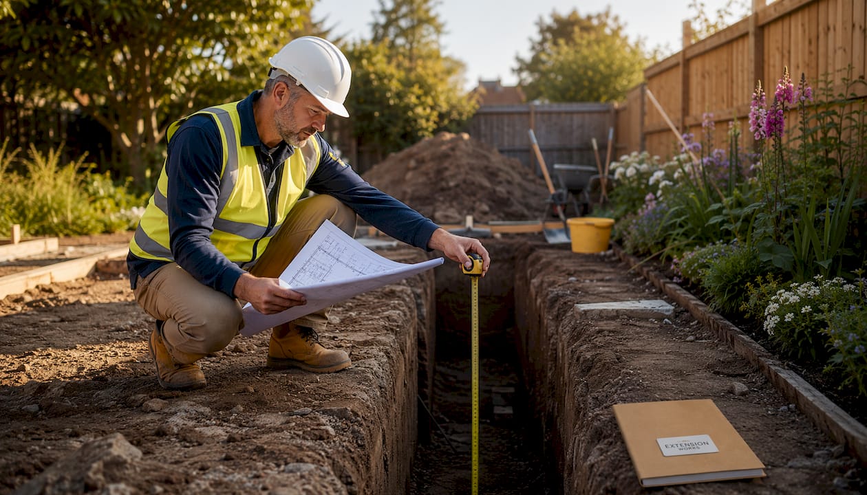
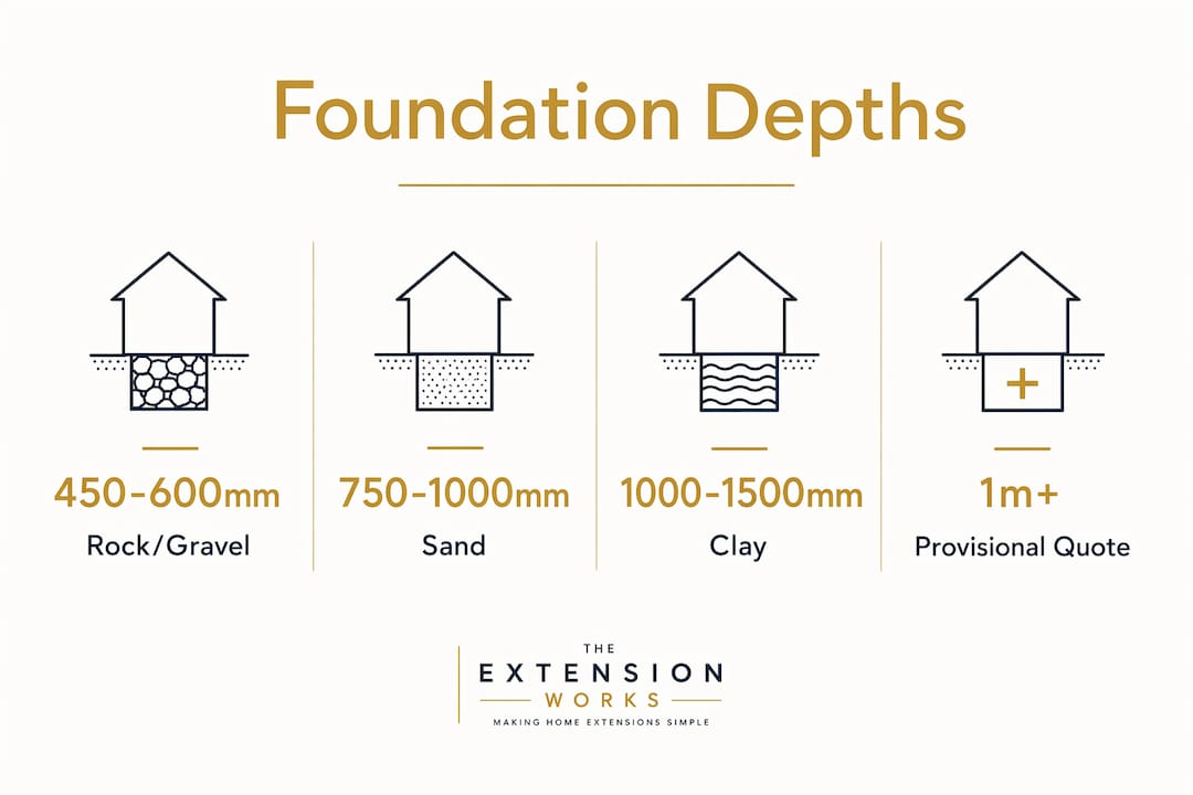
For most single-storey rear extensions on stable ground in England, you are looking at a minimum foundation depth varying by soil type, generally starting at 450–600mm on rock or dense gravel, increasing to 750–1,000mm for sand, and 1,000–1,500mm for stiff clay. Near high-water-demand trees on clay, depths may rise to 1,500–3,000mm or more. Made ground or landfill changes everything and may require piling or a raft. These are provisional starting points. The actual depth is set by Building Control after inspecting the open trench, not by a rule of thumb.
The single most important next step: dig trial holes before you commit to any price or programme. A structural engineer reads the soil profile, specifies the depth and width, and produces the drawings Building Control needs. Any quote that gives you a fixed definitive depth without trial holes is either guessing or hiding a large contingency.
Quick summary:
- Stable granular ground (rock, dense gravel): 450–600mm, often the minimum frost-protection depth
- Sand or sandy gravel: 750–1,000mm typical
- Stiff clay, no trees nearby: 1,000–1,500mm
- Clay with high-water-demand trees (oak, willow, poplar): 1,500–3,000mm+
- Made ground or fill: specialist solution required (raft, piles, or excavation to natural strata)
- Every trench is inspected by Building Control before concrete is poured; inspectors can require deeper excavation on the day
- Extra depth costs money: budget a per-metre contingency rate with your contractor before work starts
Pro Tip: Ask your contractor for the provisional depth assumption in their quote and the agreed rate per additional metre. If they cannot give you both figures, that is a red flag.
Table of Contents
- What do UK Building Regulations say about minimum foundation depth?
- How does soil type change the depth and type of foundation you need?
- How do trees affect how deep your foundations need to go?
- What do drains and neighbouring foundations mean for your foundation depth?
- How does the size and construction of your extension affect foundation depth and width?
- When does made ground or poor subsoil force a specialist foundation solution?
- What are the main foundation types used on UK domestic extensions?
- What is the process from trial holes to Building Control sign-off?
- When do you need underpinning, piling, or resin injection?
- What questions should you ask a contractor or structural engineer?
- How The Extension Works handles foundations for single-storey rear extensions
- Key takeaways
- Why getting foundations right is worth the upfront effort
- Get a fixed-price quote that includes engineer-led foundations
- Useful sources and further reading
What do UK Building Regulations say about minimum foundation depth?
The regulatory floor comes from Approved Document A (Structure), which governs all structural work in England. It does not hand you a single magic number. Instead, it sets out minimum requirements that interact with soil type, loading, and site conditions. For practical purposes, the commonly referenced minimums are 450–600mm on rock or dense gravel, 750–1,000mm for sand or sandy gravel, and 1,000–1,500mm on stiff clay, with greater depths needed near high-water-demand trees or drains. The 450mm figure is primarily a frost-protection threshold. Ground frost in England rarely penetrates deeper than 450mm, so any foundation above that level risks heave damage in a hard winter. On shrinkable clay, seasonal moisture movement is the bigger threat, which is why the minimum jumps to 1,000mm.
Building Control’s role goes well beyond checking drawings. An inspector visits the site when the trench is open and the bottom is exposed. If the material at the specified depth looks soft, wet, or inconsistent, the inspector can require deeper excavation before concrete is poured. That decision happens on the day, which is why provisional pricing matters so much.
NHBC Standards Chapter 4.2 is the reference structural engineers reach for when determining site-specific depths, particularly on clay. BS 8004, the British Standard for foundations, underpins the engineering calculations behind any compliant design. Drawings submitted to Building Control should reference both.
How does soil type change the depth and type of foundation you need?
Soil type is the primary driver of foundation design. Two sites 200 metres apart can need completely different solutions. Here is a working guide to common UK soils.
Rule-of-thumb depth ranges by soil type
| Soil type | Typical depth range | Common foundation type |
|---|---|---|
| Rock / dense gravel | 450–600mm | Strip or trench fill |
| Sand / sandy gravel | 750–1,000mm | Strip or trench fill |
| Stiff clay (no trees) | 1,000–1,500mm | Trench fill |
| High-plasticity clay (no trees) | 1,000mm+ (engineer to specify) | Trench fill or raft |
| Clay near high-water-demand trees | 1,500–3,000mm+ | Deep trench fill or piles |
| Made ground / fill | Through-fill to natural strata | Raft, piles, or deep strip |
These figures are provisional until trial holes confirm the actual soil profile. NHBC Standards Chapter 4.2 uses clay plasticity classifications to determine site-specific depths; high-plasticity clay often needs at least 1,000mm, while stable granular soils may allow 450–750mm.
Why bearing capacity and seasonal movement matter
Bearing capacity is the soil’s ability to carry load without compressing or shearing. Sandy and gravelly soils drain freely and carry load well; clay holds water and changes volume with the seasons. Shrinkable clay swells when wet and contracts when dry, creating upward pressure (heave) in winter and downward settlement in summer. A foundation that sits in the active zone of that movement will crack the structure above it.
The practical response is to get below the active zone entirely. On stiff clay with no tree influence, that usually means 1,000–1,500mm. On high-plasticity clay, the engineer may specify a trench fill solution with compressible void formers on the inside face to absorb heave forces rather than fight them.
Site indicators that flag the need for a geotechnical report
- Silted or collapsed drains visible in the garden
- Patches of standing water after rain (suggests poor drainage or a high water table)
- Visible made ground: rubble, ash, brick fragments, or uneven ground levels
- Soft or spongy ground underfoot
- Neighbouring properties with visible cracking or subsidence history
- Any site within the zone of influence of mature trees
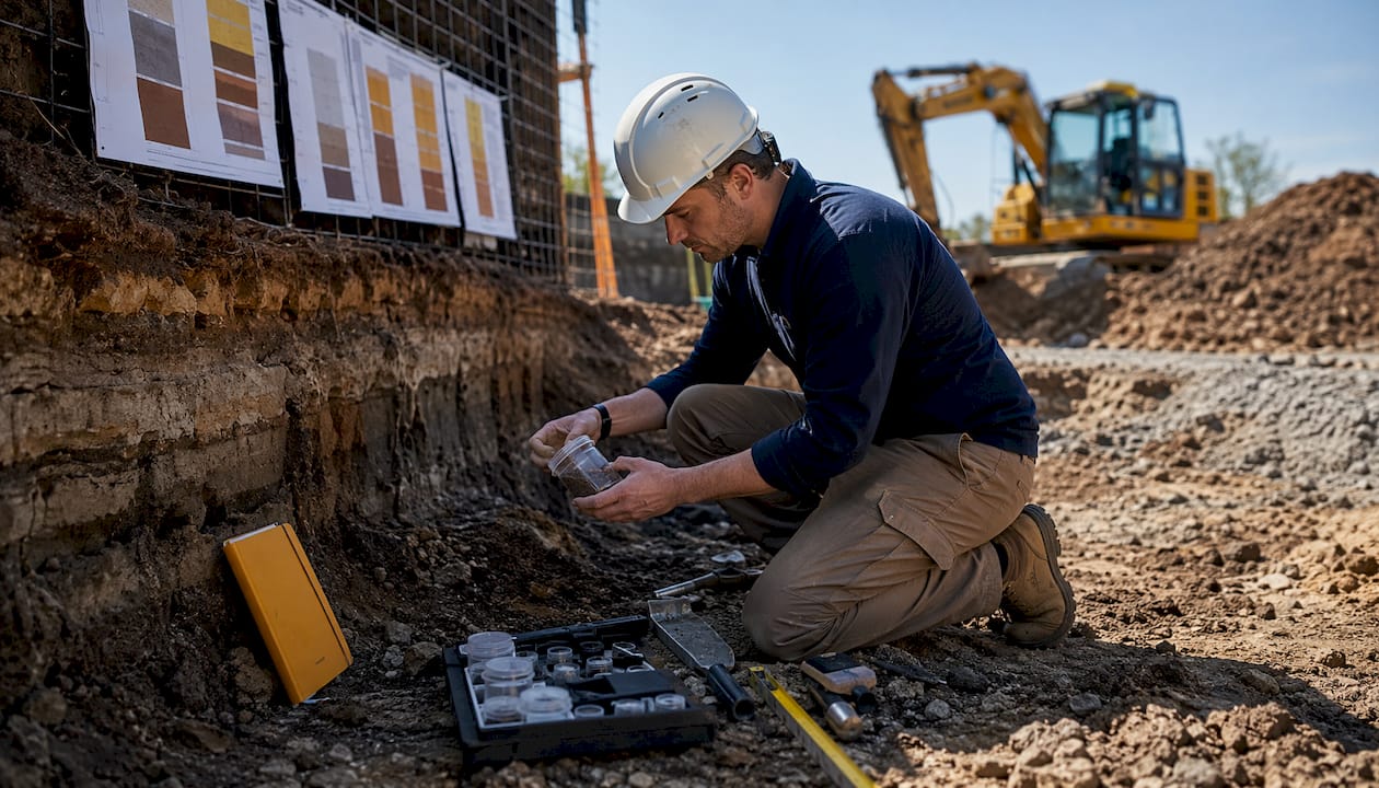
Pro Tip: When the trial pit is open, ask the engineer to describe each layer: colour, texture, and whether it smears or crumbles. Smearing means clay; crumbling means granular. That five-minute conversation tells you more than any desk study.
How do trees affect how deep your foundations need to go?
Trees on clay are the single most common reason a straightforward extension becomes an expensive one. The mechanism is simple: tree roots extract moisture from clay, causing it to shrink and settle. Remove the tree and the clay rehydrates and heaves upward. Both movements damage foundations that sit in the affected zone.
The zone of influence is typically taken as a radius equal to the tree’s mature height. A mature oak at 20 metres tall has a zone of influence extending 20 metres from its trunk. For high-water-demand species, engineers often extend that radius further. Distance from the extension matters, but so does species: a silver birch at 10 metres away is a different proposition from a willow at the same distance.
Practical depth implications on clay are significant. Where no trees are present, 1,000–1,500mm is typical. Add a high-water-demand tree within its zone of influence and that figure can rise to 1,500–3,000mm, sometimes deeper. The risk cuts both ways: a recently felled tree leaves clay that is rehydrating and heaving, which can be more damaging than the original root activity.
When to commission a BS 5837 arboricultural survey:
- Any mature tree within a distance equal to its estimated mature height from the proposed extension
- High-water-demand species within 1.5 times their mature height
- Any tree subject to a Tree Preservation Order
- Sites where a tree has been removed within the last five years
The structural engineer needs the arboricultural report to confirm species, estimated mature height, and water demand category before specifying foundation depth. Without it, the engineer will default to a conservative assumption, which usually means deeper and more expensive.
Pro Tip: Never assume a tree is “far enough away.” Measure from the trunk to the nearest point of the proposed foundation, not the nearest point of the extension footprint. The foundation trench is what matters.
What do drains and neighbouring foundations mean for your foundation depth?
Drains set a hard minimum that overrides everything else on the relevant section of trench. The rule is straightforward: your foundation must go below the invert level (the bottom of the internal bore) of any drain running alongside or crossing beneath the proposed foundation line. If the drain invert sits at 900mm and your soil would otherwise allow a 750mm foundation, that section of trench goes to at least 900mm, and typically deeper to provide a safe margin.
How to check for buried drains
- Request drainage records from your local sewerage undertaker (Thames Water, Southern Water, and similar, depending on your area)
- Check the Planning Portal for any recorded public sewers
- Commission a CCTV drain survey if records are incomplete or the site has been developed before
- Look for inspection chamber covers in the garden; they indicate drain runs
Practical steps before excavation
- Identify all drain runs within 3 metres of the proposed foundation line
- Establish invert depths from records or a drain survey
- Provide invert level information to the structural engineer before they finalise the foundation design
- Notify the sewerage undertaker if any public sewer is within 3 metres of the proposed works
- Check whether a build-over agreement is required under the Water Industry Act if the extension sits above or close to a public sewer
Building Control inspectors check drain proximity during the open-trench inspection. If a drain is discovered that was not on the drawings, work stops until the engineer revises the design. That is an expensive surprise to have on the day of the pour.
Neighbouring foundations create a separate issue. When a new extension foundation is deeper than the existing house’s footings, differential settlement becomes a real risk. Engineers commonly specify a movement joint between old and new, or design the new foundation as structurally independent, to prevent cracking at the junction.
How does the size and construction of your extension affect foundation depth and width?
Depth gets most of the attention, but width is equally important. A foundation that is deep enough to reach stable ground can still fail if it is too narrow to spread the load across the bearing area. Both dimensions come from the structural engineer’s calculations.
A single-storey masonry extension is the most common scenario. Strip foundations at 1,000–1,500mm depth are typical on stiff clay, and 450–600mm on sandy or granular ground. Width is typically 450–600mm for a single-skin or cavity wall on reasonable ground, but widens on softer soils. A two-storey extension doubles the wall load, which usually means a wider strip or a deeper trench fill to compensate.
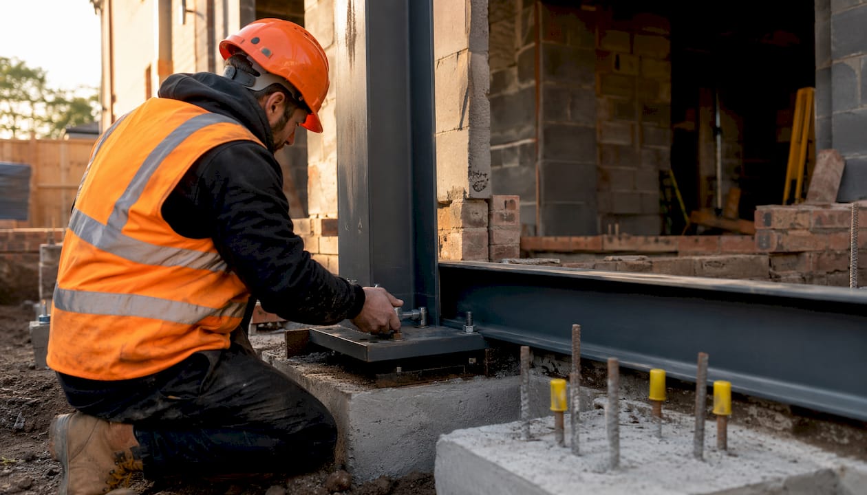
Steel or timber-framed extensions concentrate loads differently. Instead of a continuous wall load, you get point loads at column bases, which calls for pad foundations rather than a continuous strip. Pad foundations are sized individually for each column load and the bearing capacity of the ground at that point.
Structural openings matter too. A large set of bifold doors or a steel beam spanning an opening creates a point load at each end. The engineer will check whether the existing foundation at the bearing point can carry that load, or whether a pad or local thickening is needed.
The drawings Building Control receives must show foundation type, depth, width, and concrete specification. A C25 or C30 mix is standard for most domestic strip foundations; sulphate-resistant cement is specified when the ground investigation reveals sulphate-bearing soils, which is common on some clay and made-ground sites.
When does made ground or poor subsoil force a specialist foundation solution?
Made ground is any material that has been placed by human activity rather than deposited naturally: demolition rubble, ash, domestic waste, old fill from previous development. It compresses unevenly under load, drains poorly, and can contain contaminants. A standard strip foundation sitting in made ground will settle differentially and crack the structure above it.
The practical options when made ground is present:
- Excavate through fill to natural strata. If the made ground is shallow (say, 1–2 metres), digging through it to reach firm natural soil is often the most straightforward solution, though muck-away costs rise sharply with volume.
- Raft foundation. A reinforced concrete slab spanning the whole footprint distributes load broadly and tolerates some differential movement. Suitable when made ground is shallow and the natural ground below has reasonable bearing capacity.
- Mini-piles or screw piles. Piles driven or bored to firm strata below the made ground, then capped with a ground beam. Higher upfront cost but minimal excavation and fast installation.
- Mass concrete underpinning. Less common for new extensions; more relevant when strengthening existing shallow footings.
Made ground requires either excavation through fill to natural ground or specialist foundations; engineer-led design is mandatory in every case.
Relative cost and programme impact:
- Excavation to natural strata: moderate cost, moderate programme impact; depends heavily on depth and muck-away rates
- Raft foundation: moderate cost, low disruption, faster programme than deep excavation
- Piling: higher upfront cost, but often the fastest solution on deep or contaminated fill; specialist contractor required
Pro Tip: If your garden has ever been used as a dumping ground, or the property sits on a former orchard, allotment, or industrial site, commission a desk study before you get quotes. A Phase 1 environmental report costs a few hundred pounds and can save you from a very expensive surprise mid-excavation.
What are the main foundation types used on UK domestic extensions?
Strip and trench fill foundations
Strip foundations are the default for load-bearing masonry walls. A trench is dug to the specified depth, concrete is poured to a minimum width, and the masonry sits on top. Trench fill is a variant where the trench is filled almost to ground level with concrete, eliminating the need for brickwork below ground. Trench fill is faster and reduces the risk of trench collapse on loose soils.
Typical depth: 450–600mm on rock or dense gravel, 750–1,000mm on sand, and 1,000–1,500mm on stiff clay (greater depths on clay near trees). Typical width: 450–600mm on good ground, wider on softer soils. Concrete specification: C25 or C30; sulphate-resistant mix where ground investigation indicates sulphate presence.
Raft foundations
A reinforced concrete slab spanning the full footprint of the extension. Rafts are used on poor or variable ground where a strip foundation would settle unevenly. They require careful design to control cracking and deflection, and the ground beneath must be prepared (compacted hardcore, blinding layer) before the slab is poured.
Pad foundations
Isolated concrete pads at column or post positions. Used for steel or timber-framed extensions where loads are concentrated at points rather than spread along a wall. Each pad is sized for the column load and the bearing capacity of the ground at that location.
Piled foundations
Piles transfer load to firm strata at depth, bypassing weak or made ground near the surface. Mini-piles (small-diameter bored or driven piles) are the most common choice on domestic extensions. Screw piles are a faster, lower-vibration alternative on suitable ground. Both require a ground beam to distribute load from the wall above to the pile heads.
| Foundation type | Typical depth | Best ground conditions | Key consideration |
|---|---|---|---|
| Strip / trench fill | 450–600mm (rock/dense gravel), 750–1,000mm (sand), 1,000–1,500mm (stiff clay), 1,500–3,000mm+ (clay near high-water-demand trees) | Rock, gravel, sand, stiff clay | Width as important as depth |
| Raft | Shallow | Variable or poor ground | Requires careful ground preparation |
| Pad | Varies by load | Any, at column positions | Point loads only; needs ground beam |
| Mini-piles | 3m+ | Made ground, soft clay, deep fill | Specialist contractor required |
What is the process from trial holes to Building Control sign-off?
The process is more structured than most homeowners expect, and understanding it helps you hold contractors accountable.
- Site visit and desk study. The engineer reviews the site, checks available records (drainage, previous development, tree survey if needed), and identifies likely ground conditions before any digging.
- Trial pits. Typically 1.5–2.5m deep, dug by a mini-digger. The engineer inspects each pit face, records soil layers, and takes samples if needed. This is where provisional depth assumptions are confirmed or revised.
- Engineer design. The engineer produces foundation drawings (depth, width, concrete specification, drainage clearance details) and structural calculations. These go to Building Control with the full structural package.
- Excavation. The contractor digs to the specified depth. On clay sites deeper than approximately 1.5m, void formers or compressible materials may be installed on the inside trench face to manage heave, with polythene lining to protect the concrete.
- Building Control inspection. The inspector visits the open trench before any concrete is poured. If the bottom looks soft or inconsistent, deeper excavation is required. This is the point where provisional budgets get tested.
- Pour and sign-off. Once the inspector is satisfied, concrete is poured. The inspector returns at key stages (damp-proof course, structural frame, roof) and issues a completion certificate at the end of the project.
Documents the engineer should provide
- Ground investigation report (trial pit logs, soil descriptions, any lab results)
- Foundation drawings: type, depth, width, concrete specification, drainage clearance
- Structural calculations demonstrating compliance with Approved Document A
- Specification notes: concrete mix, sulphate class if relevant, void former details for deep clay trenches
- Any drainage or build-over agreement documentation
Reputable quotes state a provisional depth (often 1.0m) plus a pre-agreed rate per extra metre; the definitive depth is set after trial holes and Building Control inspection. On stiff clay, anticipate a typical depth of 1,000–1,500mm, with at least 500mm of contingency budgeted if trees or drains are present.
When do you need underpinning, piling, or resin injection?
Underpinning is a standard engineering solution, not a sign that something has gone catastrophically wrong. It is used when existing shallow footings cannot carry additional load from a new extension, or when poor ground requires load transfer to deeper strata.
Main triggers for specialist methods:
- Existing house foundations are shallower than the new extension requires, creating differential settlement risk
- Poor bearing strata are too deep for economical strip excavation
- Made ground, landfill, or contamination makes conventional excavation impractical
- Localised voids or weak spots identified during trial pitting
- High water table making open excavation unstable
| Method | Best use case | Disruption level | Typical programme impact |
|---|---|---|---|
| Mass concrete underpinning | Strengthening existing shallow footings | High (sequential bays) | Weeks |
| Mini-piles | Deep poor ground, made ground | Low to moderate | Days to a week |
| Screw piles | Accessible sites, no vibration constraint | Low | Days |
| Resin / grout injection | Localised voids, weak spots | Very low | Days |
Modern underpinning methods such as mini-piles and resin injection reduce disruption significantly compared with traditional mass concrete approaches, but they require specialist designers and contractors. A generalist builder cannot specify or install these systems safely.
Warranty expectations: specialist foundation contractors should provide a written guarantee on their work, separate from the main contractor’s workmanship warranty. Ask for it before signing any contract.
What questions should you ask a contractor or structural engineer?
The right questions separate contractors who genuinely understand foundation design from those who are guessing and hoping Building Control does not push back.
Credentials and evidence to expect:
- In-house foundation team or a named specialist subcontractor with verifiable experience
- Evidence of engineer-led design: named engineer, professional indemnity insurance, and drawings signed off by that engineer
- Public liability insurance of at least £2 million
- Workmanship warranty covering foundations specifically, not just the superstructure
- Previous Building Control completion certificates they can share
Questions to ask during quotation:
| Question | What a good answer looks like |
|---|---|
| Are trial holes included in your quote? | Yes, or priced separately with a clear cost |
| What is your provisional foundation depth assumption? | A specific figure (e.g. 1.0m) stated clearly |
| What is your rate per additional metre of excavation? | A clear per-metre figure agreed upfront |
| Who signs off with Building Control? | Named engineer or in-house technical lead |
| How do you handle drains or trees discovered during excavation? | A clear process, not “we’ll deal with it” |
| What concrete specification do you use? | C25 or C30 minimum; sulphate-resistant if relevant |
Red flags:
- A fixed definitive depth quoted without any mention of trial holes
- No provisional depth stated, or a vague “it depends” with no follow-up process
- Unusually low prices that exclude trial holes, muck-away, or extra excavation
- Vague reference to Building Control sign-off with no named inspector or process
- Generalist builders who cannot interpret geotechnical data or who dismiss the need for an engineer
Pro Tip: Ask to see a previous foundation drawing from a comparable project. A contractor who has worked with a structural engineer will have one. A contractor who has not will change the subject.
How The Extension Works handles foundations for single-storey rear extensions
The Extension Works manages the full foundation process in-house, from the initial site survey through to Building Control sign-off, as part of its fixed-price design-and-build service for single-storey rear extensions.
The process in practice:
- Instant online quote with a provisional foundation depth assumption built into the price
- Site survey and trial holes carried out before construction begins, with the structural engineer reviewing soil conditions on site
- Engineer-produced foundation drawings and calculations submitted to Building Control as part of the full structural package
- In-house construction team carries out the excavation, with a pre-agreed per-metre rate for any additional depth required by Building Control
- Building Control inspection at the open-trench stage, with the team managing any required adjustments
- 12-month workmanship warranty covering the completed extension, including foundations
Where ground conditions require a different approach (raft, mini-piles, or underpinning), The Extension Works presents the options to the homeowner with clear cost and programme implications before any work begins. There are no hidden extras after the trench is open.
Documentation provided at handover:
- Building Control completion certificate
- Foundation drawings and structural calculations
- Ground investigation notes from the trial hole stage
- Warranty documentation
The extension foundation process at The Extension Works is designed so homeowners never have to chase an engineer or interpret a geotechnical report themselves. The technical decisions are managed by the in-house team; the homeowner sees the outcome and the price.
For homeowners who want to understand how extension planning rules interact with foundation decisions, particularly on boundary proximity and permitted development depth limits, that information is covered in the planning guidance.
Key takeaways
Foundation depth for extensions in England is never a single fixed number: it is determined by soil type, tree proximity, drain invert levels, and Building Control inspection of the open trench, with trial holes and an engineer’s calculations as the non-negotiable first step.
| Point | Details |
|---|---|
| Minimum depths vary by soil | 450–600mm on rock/dense gravel; 750–1,000mm on sand; 1,000–1,500mm on stiff clay. |
| Trees on clay push depths much deeper | High-water-demand species can require 1,500–3,000mm or more on clay soils. |
| Building Control sets the final depth | Inspectors can require deeper excavation after viewing the open trench on the day. |
| Trial holes are non-negotiable | No reputable contractor fixes depth without digging trial holes and engaging an engineer. |
| The Extension Works | Manages trial holes, engineer design, and Building Control sign-off in-house with a 12-month workmanship warranty. |
Why getting foundations right is worth the upfront effort
The most expensive foundation problems are the ones discovered after the concrete is poured. A trench that is 200mm too shallow on shrinkable clay does not fail immediately; it fails two winters later when the clay heaves and the extension wall cracks at the junction with the house. By then, the builder has moved on and the homeowner is arguing about warranty coverage.
The contractors who cause these problems are rarely incompetent in every other respect. They are often experienced builders who have done dozens of extensions and never had a problem, so they stop treating foundation depth as a variable that needs investigation. They quote a depth, dig to it, and pour. Building Control signs off because the trench looks acceptable on the day. The problem only emerges when conditions change.
Insisting on trial holes and an engineer-led design is not about distrust. It is about having a documented basis for every decision, so that if something does go wrong, there is a clear record of what was specified, why, and by whom. That record protects the homeowner and the contractor.
One more thing: a quote that excludes trial holes is not a cheaper quote. It is a quote that has hidden the cost of the unknown. The per-metre contingency rate is where that cost reappears, usually at the worst possible moment.
Get a fixed-price quote that includes engineer-led foundations
If you are planning a single-storey rear extension and want a price that accounts for foundations properly, The Extension Works offers an instant online quote with a provisional foundation assumption built in and a clear per-metre rate for any additional depth.

Every project includes a site survey, trial holes, structural engineer drawings, and Building Control management as part of the fixed VAT-inclusive price. No separate engineer to find, no surprise invoices when the trench goes deeper than expected. The 12-month workmanship warranty covers the completed extension from foundations to roof.
Get your instant extension quote and see a live 3D model of your proposed extension before committing to anything.
Useful sources and further reading
Primary UK regulatory and guidance sources you should expect to see referenced on engineer drawings and Building Control submissions:
- Approved Document A (Structure) — the statutory minimum requirements for structural work in England, including foundations
- NHBC Standards Chapter 4.2 — the practitioner reference for site-specific foundation depths, particularly on clay
- BS 8004 — the British Standard for foundations, underpinning the engineering calculations behind any compliant design
- Building Control guidance: CNCD-050 Simple Extension Easy Guide — plain-language summary of foundation minimums and precautions
- Party Wall etc. Act 1996 guidance — relevant when foundations are close to a shared boundary or neighbouring structure
- PorthouseDean: Single Storey Extension Structural Guide — practical structural overview for single-storey masonry extensions
Further reading from The Extension Works:
- Foundations for extensions: the complete UK guide
- Rear extension cost in 2026: a UK homeowner’s guide
- Extension cost per m² in the UK
- Planning permission drawings: a homeowner’s guide
- Rear extension planning: UK rules and local guide
Recommended
- Foundations for extensions: the complete UK guide — The Extension Works
- Permitted Development & Extension Rules 2026 — How Big Can You Build? | The Extension Works
- Building work hours: a homeowner’s guide to faster extensions — The Extension Works
- Rear extension planning: UK rules and local guide 2026 — The Extension Works